Hardware beta testing has begun!
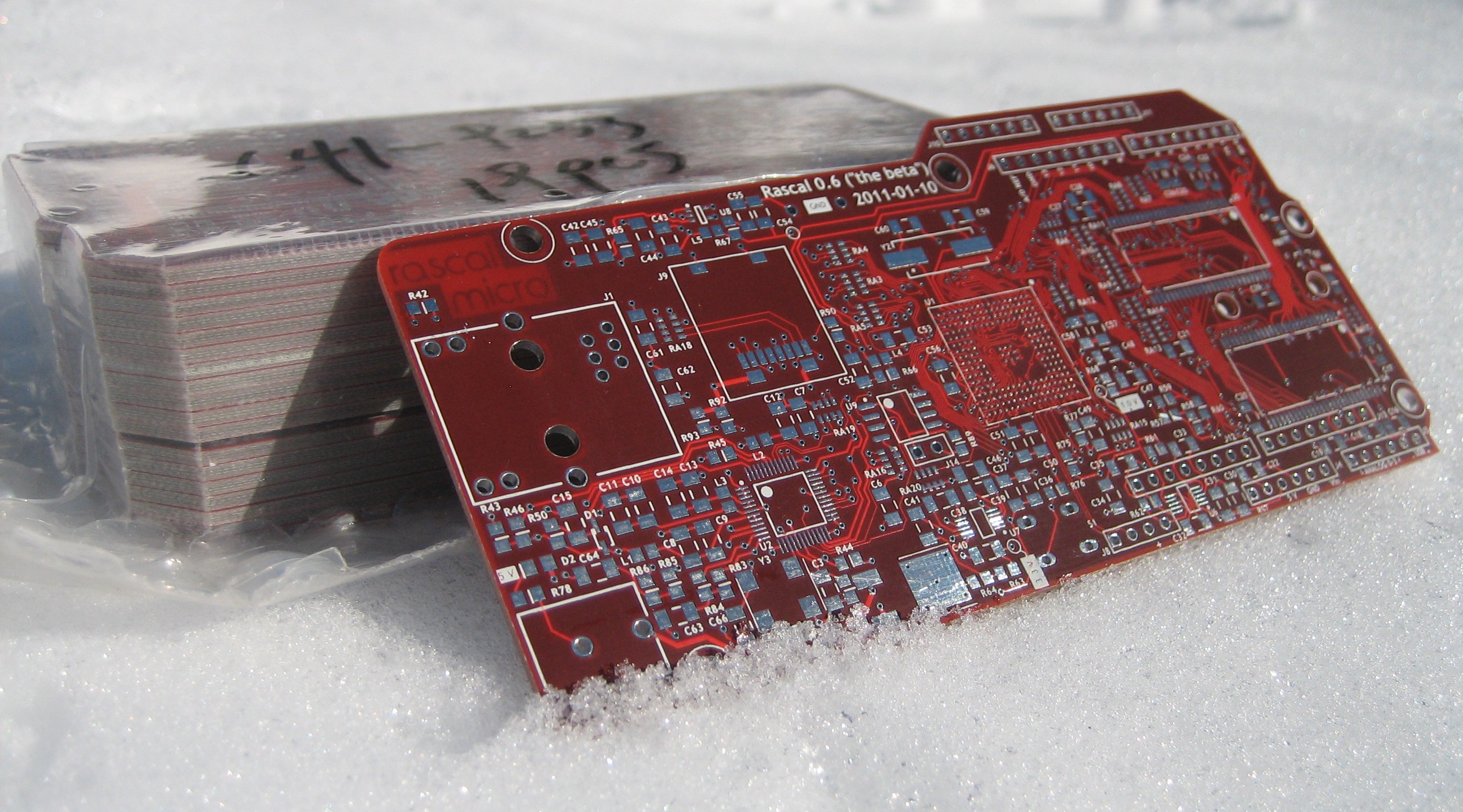
I am pleased to announce that a box of 16 Rascals arrived from China on Tuesday, the first Rascal sale has been made, and the first Rascal has been shipped to a Distinguished Gentleman in the District of Columbia. I've been working on the Rascal for exactly a year as of tomorrow. It's taken longer than I expected, but the result is also far more awesome than what I originally had planned.
A few of the beta units are being tested by courageous individuals over the next few weeks. When the Rascal software has matured, I'll send out an email inviting normal people to join the vanguard of internet gadgeteers. Sign up for the mailing list if you're interested.
Rascal demo ready for action
In related news, there's now a demonstration of a Rascal connected to the web.
It's a simple setup that reads the voltmeters ("A/D converters") on the Rascal and graphs the results. The voltmeters are connected to a relay, a capacitor, and a temperature sensor. You can turn the relay on and watch the capacitor charge up, or turn it off and watch the capacitor discharge. It's good example of the basic capabilities of the Rascal-- monitoring and control through the web.
(I'll keep the demo up for the next day or two, but if you're reading this in mid-April, or 2016, or similar, it will probably be gone.)
I announced this demo via email to a couple of my engineer friends earlier today, and within 1 minute, the relay on my desk that you control with the demo was clicking on and more wildly. As the afternoon went on, multiple people attempted to use the relay to send me messages in Morse code. (I don't know Morse code well enough to have translated them on the fly, but I've been told that one of them said H-I-F-R-O-M-M-A-T-T.)
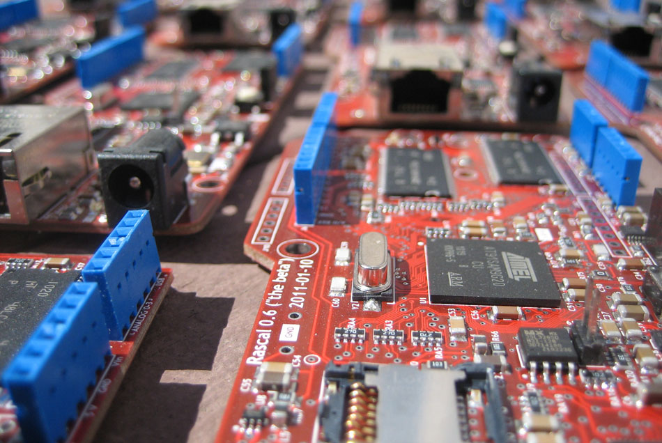
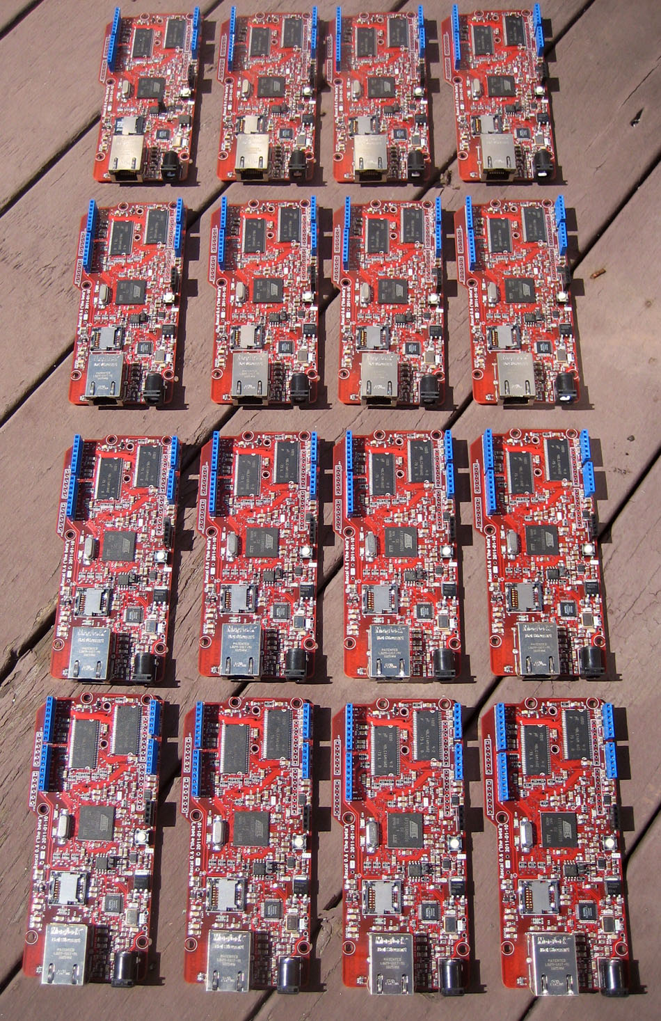
Look at this beautiful fleet of Rascals!
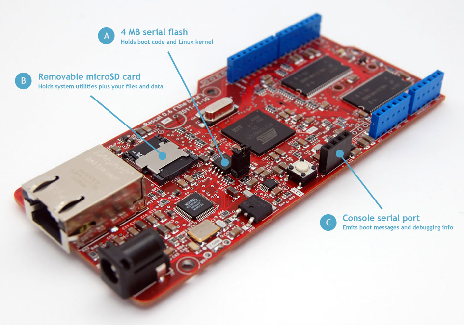
Toggling pins on the AT91SAM9G20 with U-boot
I recently faced a problem with the Rascal where I needed to test whether some of the pins on the processor were damaged by bad soldering. A couple of the pins used for talking to the Ethernet transceiver were acting weird, and I thought there might be a short circuit under the BGA package. It turned out that the problem was in software, but as part of the debugging, I figured out how to toggle pins from the command line prompt of the U-boot bootloader.
A little background about microcontrollers
Microcontrollers have various hardware peripherals built in-- hardware for talking to serial ports, timers, and the like. All of these features are controlled by bits stored in registers in memory. I'm using words like "bits" and "registers" like they're commonplace, but don't worry if you aren't sure exactly what they mean. When we get to the code section, you can see the patterns of how this stuff works even if you don't understand all the details.
In the AT91SAM9G20 controller I'm using on the Rascal, there is a group of 32 pins called Port A. There are also two other 32-pin groups called Port B and Port C which are similar, but with slightly different features.
The pins in Port A can all be used as general purpose input or output pins ("GPIO"). To make a pin function as an output, you have to do 3 things:
- Turn off all its peripheral functions.
- Set it to be an output.
- Set its voltage to be high or low.
While the details I'll describe below are tailored to the 9G20, the three steps are similar in most microcontrollers.
I'll show how to do each step, but first we need a little explanation of how we talk to the hardware.
Registers that control hardware
A register means a collection of 32 bits in the processor's internal memory, numbered from 0 to 31. If you think in bytes, you could also think of the 32 bits as 4 bytes of 8 bits each. The registers that control Port A reside near the top of the processor's memory space, in the range of 0xfffff400-fffff4b0. In each register, the 32 bits correspond to the port's 32 pins. For example, to configure the Port A pin called PA17, you need to manipulate bit 17 in each of the relevant registers. (If you're curious, the controller datasheet maps names like PA17 to physical pins (well, solder balls) in Table 4-1.)
Conveniently, U-boot has a command (md, for "memory dump") that lets you see the values stored in all the relevant bits. Here's what happens on the command line when I use md to read the contents of the registers that control Port A, 0xfffff400-fffff4b0.
language-bash
U-Boot> md fffff400
fffff400: 00000000 00000000 fe400030 00000000    ........0.@.....
fffff410: 00000000 00000000 01800000 00000000    ................
fffff420: 00000000 00000000 00000000 00000000    ................
fffff430: 00000000 00000000 00000000 c0680efa    ..............h.
fffff440: 00000000 00000000 00000000 ffffffff    ................
fffff450: 00000000 00000000 01800000 00000000    ................
fffff460: 00000000 00000000 01bff00f 00000000    ................
fffff470: 00000000 00000000 00000000 00000000    ................
fffff480: 00000000 00000000 00000000 00000000    ................
fffff490: 00000000 00000000 00000000 00000000    ................
fffff4a0: 00000000 00000000 00000000 00000000    ................
fffff4b0: 00000000 00000000 00000000 00000000    ................
fffff4c0: 00000000 00000000 00000000 00000000    ................
fffff4d0: 00000000 00000000 00000000 00000000    ................
fffff4e0: 00000000 00000000 00000000 00000200    ................
fffff4f0: 50494f32 20202020 00002017 00000204    2OIP    . ......
By default, md reads 256 bytes starting at the address you specify, so actually I get a little more than I need. The leftmost column, with all the f's, is a list of addresses, counting bytes. The rightmost column, with all the periods, is an ASCII translation of the data in memory. In this case, we're not storing ASCII text in memory, so we can ignore that.
The four columns of mostly zeroes in the middle represent the data itself. Each character, which can range from 0-9 and a-f, represents 4 bits. Each group of 8 characters represents a single register of 32 bits. This is bewildering if you haven't heard it before, so let's look at an example.
Consider the register starting at byte address 0xfffff408. This is the register in the top row that contains fe400030. This is the register called the peripheral status register or PIO_PSR. Each bit in this register describes the status of one pin. If the bit is high, it means that the pin can be used as GPIO; if it's low, one of its peripherals is turned on. If we convert the hex value 0xfe400030 to binary, we can see which peripherals are on. I've added spaces after every 4 bits to make matching with hexadecimal characters easier. By convention, we list the bits from highest (31) to lowest (0). 0xfe400030 = 1111 1110 0010 0000 0000 0000 0011 0000 in binary. We have 10 bits that are high, so there are 10 pins that are set as GPIO right now. Here's the list: pins 31-25, pin 21, and pins 1-0.
For toggling pins, there are three sets of three registers (9 registers in total) that we care about. I'll list them first and then explain the pattern to them.
language-bash
PIO_PER (peripheral enable register) at 0xfffff400
PIO_PDR (peripheral disable register) at 0xfffff404
PIO_PSR (peripheral status register) at 0xfffff408
PIO_OER (output enable register) at 0xfffff410
PIO_ODR (output disable register) at 0xfffff414
PIO_OSR (output status register) at 0xfffff418
PIO_SODR (set output data register) at 0xfffff430
PIO_CODR (clear output data register) at 0xfffff434
PIO_ODSR (output data status register) at 0xfffff438
The pattern is this: enable, disable, status. You write to one of the first two registers to enable or disable something; you see the results in the third register. The first three registers are the peripheral enable, peripheral disable, and peripheral status registers. The second three are the same pattern, but for determining whether the pin is an input or an output. The last three control for the voltage (high or low) on the pins, assuming the pins have peripherals disabled and are set as outputs. The naming of the last three breaks the enable, disable, status pattern, but the functionality where the first two are for control and the third is for results continues.
Let's say I want to toggle pin 3 on port A back and forth between high and low. I'd use three commands, one for each of the three steps listed previously. In all cases, I just want to affect pin 3, so in my command, I'll make all the bits low except for bit 3. In binary, that looks like this: 0000 0000 0000 0000 0000 0000 0000 1000. Convert that to hex and you get 0x00000008. (The mathematicians among you will note that 23 = 8.)
language-bash
U-Boot> mw fffff400 00000008 # Step 1: enable GPIO on pin 3, i.e. disable the peripherals
U-Boot> mw fffff410 00000008 # Step 2: make pin 3 an output
Now we're ready to toggle!
language-bash
U-Boot> mw fffff434 00000008 # Step 3: set pin 3 low
U-Boot> mw fffff430 00000008 # Step 3 (again): set pin 3 high
U-Boot> mw fffff434 00000008 # Step 3 (again): set pin 3 low
U-Boot> mw fffff430 00000008 # Step 3 (again): set pin 3 high
If everything worked, you've just toggled a pin.

 If you're interested in the Rascal, you should follow the Rascal on Twitter here, or add your email address to the announcement list on the main page of the Rascal website. There's also a quick video interview of me explaining how the Rascal works. It was shot by Chris Connors at the 2011 mini-Maker Faire in Cambridge, MA, USA.