Dynamic image listing in PHP
I've been working pretty hard on a top secret project for the last couple of months, so the blog posts have been a little scarce. More details about the top secret project (TSP) shortly, but in the meantime, here's a little PHP script I wrote this morning.
Having switched from Wordpress to Jekyll (a blog compiler, if you will), I needed a way to quickly browse a directory of images on a webserver and copy links to the images for insertion into blog posts. The PHP script below, if saved as index.php into a directory of images you want to browse, will create a page showing 200-pixel wide versions of all the images in rows of 5. You can tweak the image size and row length by changing the 200 and 5 in the script.
It's not kind on bandwidth, as it makes you download all your images, but it's simple. Save the code below as index.php with your images, and then browse to that file in your image directory (something like http://yoursite.com/img/index.php). Assuming your webserver has the PHP engine running, you'll see rows of images. You can then grab links by right-clicking and paste them wherever you like.
The code
```
(lang=html+php)
Images
\n";
echo "\t\t\n";
$i = 0;
if ($handle = opendir(".")) {
while (false !== ($file = readdir($handle))) {
if (strstr($file, "png")||
strstr($file, "jpg")||
strstr($file, "bmp")||
strstr($file, "gif")) {
echo "\t\t\t | \n";
$i++;
if ($i%5 == 0) {
echo "\t\t
\n\t\t\n";
}
}
}
closedir($handle);
}
echo "\t\t
\n";
echo "\t\n";
?>
```
Driving high-power LEDs
While waiting for the Rascal to be assembled by robots in Colorado, I designed a small circuit board that plugs into the top of the Rascal for driving high-power LEDs. In the last decade, clever engineers have figured out how to make LEDs that can handle around 100 times the current of the typical LED from the 90's. This is great if you want to make a small, really bright light. Unfortunately, it also means that you get a little more advanced with drive circuitry to avoid your control system burning up when at full power.
My brother is a neuroscientist at the University of Michigan; he spends a lot of time shining lights of various colors onto retinas to try to learn how they work.
Most LED drivers vary the intensity of light by using what's called pulse-width modulation (PWM). The basic concept is that you switch something full on and full off really fast, you can control the average power by changing how long you delay between switches. Suppose you have an LED that can handle 100 mA at full brightness. If you wanted to run it at half brightness with PWM, you might switch it on for 2 milliseconds, and then off for 2 milliseconds. Repeat that 4 millisecond pattern 250 times per second, and the LED will look about half-brightness. If you wanted to go to 25% brightness, you could go to 1 millisecond on and 3 milliseconds off. Microprocessors, like the one found on the Rascal, are good at switching things on and off quickly and precisely.
The only problem is that if you're a retinal neuroscience researcher, you worry that PWM might affect your results in unexpected ways. You already know that light pulses at frequencies of 5-10 Hz cause strange things to happen to retinas. You can't actually see the difference between PWM and linear control with your own eyes, but being a retinal neuroscience researcher, you don't trust your own eyes at all. You'd rather control current directly.
What we were aiming for
After talking over the requirements with my brother for a while, here's what we were aiming for.
- Control LED current using smooth variation in series resistance, not modulated pulses
- Exact LED output needed is unknown, but we think 1000 mA will do it
- Interface with 6-pin connector on QImaging Retiga 1300i camera to trigger camera during brief LED flash
- LED illumination time should be variable from 100 ms to 5 s, accurate to within 10 ms
- We want to be able to handle green, blue, and UV LEDs
The LEDs we're using
We decided to use LEDEngin's LZ1-10xx05 series of 5 W LEDs on pre-fabbed metal-core PCBs
- Green (523 nm): LZ1-10G105, Mouser 897-LZ110G105, $10.80 in qty. 1, 1000 mA, 4.5 V, 165 lm output
- Blue (465 nm): LZ1-10B205, Mouser 897-LZ110B205, $9.90 in qty. 1, 1000 mA, 3.6 V, 45 lm output
- UV (400 nm): LZ1-10UA05, Mouser 897-LZ110UA05, $30.60 in qty. 1, 700 mA, 3.9 V, 130 mW output
- UV (368 nm): LZ1-10U605, Mouser 897-LZ110U605, $46.80 in qty. 1, 700 mA, 4.1 V, 550 mW output
For testing, we got one of the recommended Cooler-Master ECB-00529-01-GP heatsinks, but in the final design, the metal-core PCBs will be mounted to a large aluminum plate that interfaces to the microscope. If need be, we'll add a heatsink to the back of the plate.
Controlling the LEDs
Controlling a 5 W LED is trickier than I expected. My first thought was to use an AD5231 digital potentiometer in series with the LED to control the current. (Ah, the naïveté!) The resistance of the chip ranges from 15 ohms to 10,000 ohms in 9.8 ohm steps. This gives excellent control at low currents, but coarse control as the current increases, because at constant voltage, the current scales with the reciprocal of the resistance.
Really, we needed something that would vary the resistance between around 5 ohms and 50 ohms, and then another series element that acts like a switch. I thought that maybe three of these AD5231's in parallel would work. Running with a 9 V supply, we'd dissipate around 4 V in the LED, leaving 5 V @ 1000 mA in the pots. That's 5 W across the 3 pots, or 1.7 W per pot. At peak power, the current would be split evenly between the three pots at 330 mA each. Unfortunately, the pots fry at 20 mA, so that's not even close.
For the series element acting like a switch, the two major choices are bipolar junction transistors (BJTs) and metal oxide semiconductor field effect transistors (MOSFETs). BJTs can go into thermal runaway when paralleled because their forward voltage drop decreases with as they heat up. This means that a hot transistor pulls more and more current until it burns. MOSFETs have the inverse characteristic-- their forward voltage drop increases as they heat up, so they tend to be self-limiting.
Spelunkers to the rescue!
In the end, we used a circuit based on a circuit designed by a caver in England by the name of Brian Pease. His design is intended for use in a battery-powered headlamp (such as those used in spelunking). It has the cool characteristic that while the battery is healthy, it allows dimming the LEDs. As the battries die, it bypasses the dimmer circuitry and drives the LED at full power, which will presumably be quite dim at this point.
Our circuit uses the same basic design, but with the AD5231 digital pot inserted in place of the manual pot in the original circuit. The PCB we made has three of these circuits so we can control three LEDs at the same time.
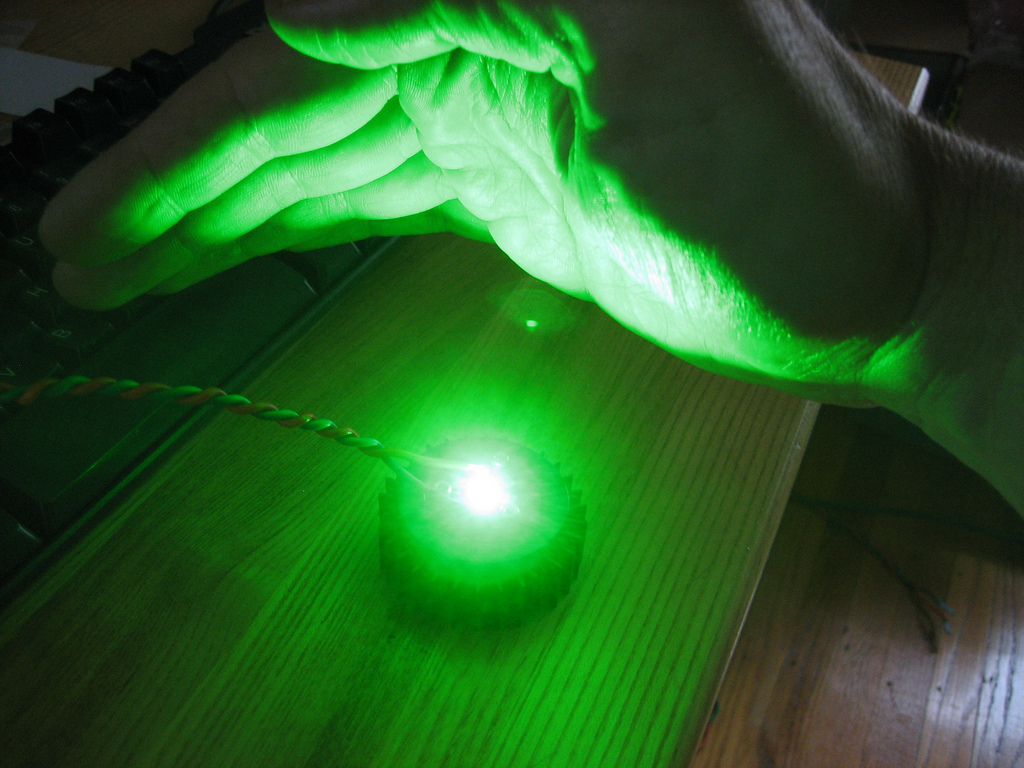
We'll have more details when the circuit boards arrive. In the meantime, here's a picture of one of the green LEDs running at around 10% of maximum brightness, controlled by a prototype circuit built on a breadboard.
It lives!
The circuit boards for the second version of the Rascal, which fixes a couple of hardware errors in the first version, arrived last week. I checked that a few new component footprints are correct and then sent them off for assembly. They should be ready for testing on Monday, August 16, 2010.
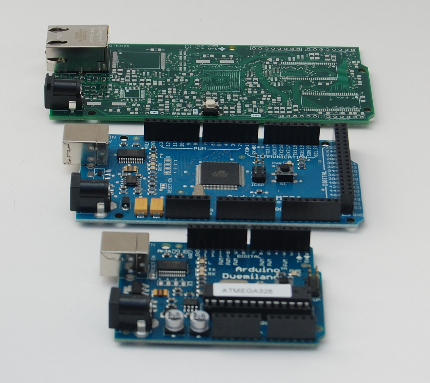
The second Rascals are substantially smaller than the first revision. The outline, connector, and mounting hole placements match the Arduino's on both ends, though the Rascal is longer. I was aiming to get the total area below 10 in2.
In the meantime, I've developed the first Rascal peripheral, an Arduino-compatible shield for driving high-power LEDs. The first prototypes were supposed to arrive today, but Fedex reports that one of their planes was struck by lightning, so it was not ready to make the subsequent delivery.
First prototypes in hand
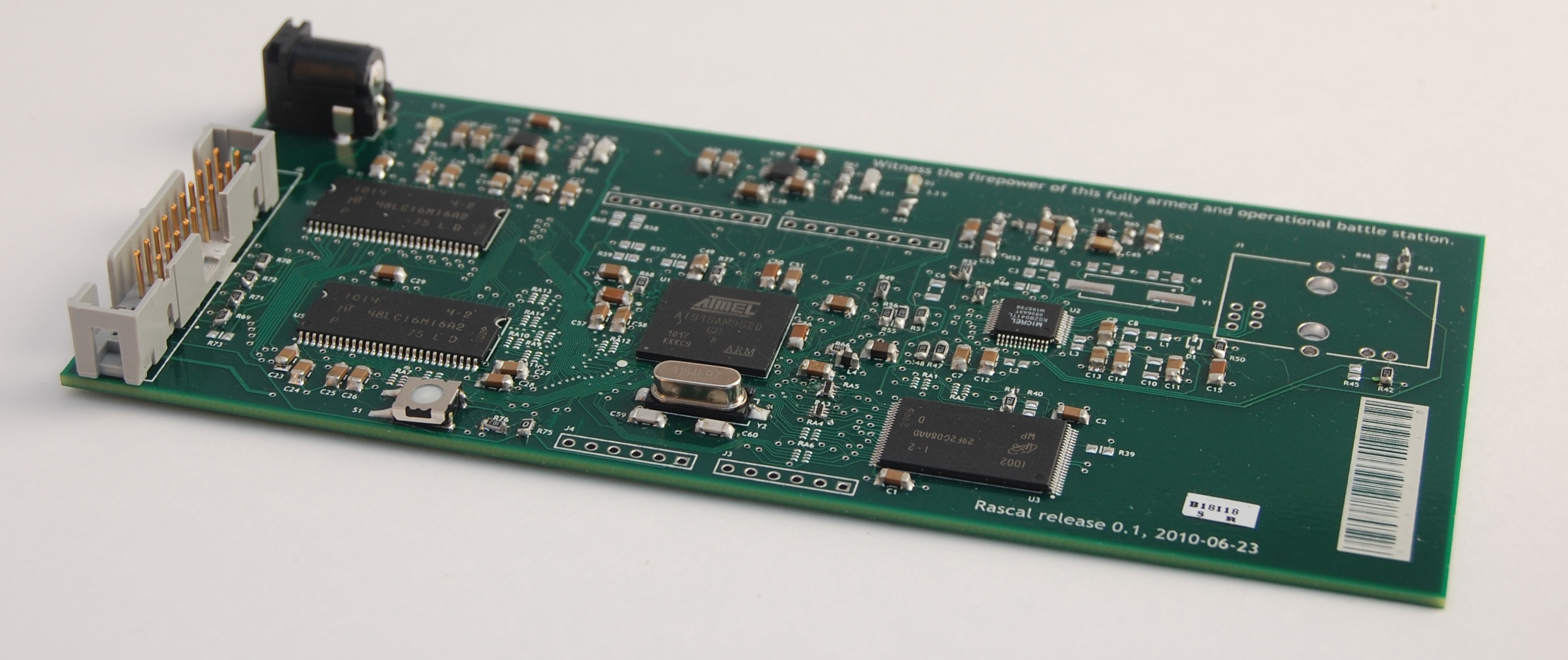
The first batch of Rascals arrived fresh from the assembler a few days ago (July 14, 2010, for the historical record). I had an assembly house in Colorado solder all of the large chips, including the slightly scary BGA package. Thanks to a microscope from GreenMountain, I was able to solder the rest of the passive components myself. Initial power-up went well-- both of the switching DC/DC converters worked, and the power LEDs lit up. I discovered I had two pins switched on the linear regulator, but I was able to cut some traces with an X-acto knife and rewire the pins correctly.
After the regulator was working, I connected to the processor using the JTAG connector (that big gray thing) and was able to download and execute code. I believe this instilled exultation at the time.
Then, I was able to locate more precisely the limits of my soldering capabilities – I verified that I am not able to solder arrays of 4 x 0402 resistors without bridging adjacent traces. As I was investigating the effects of this on the memory buses, I noticed that I had also invented a new method of counting to eight: 1, 2, 3, 4, 5, 7, 6, 8. The results of this novel method were that two of the bus lines were swapped for all 14 resistor arrays. I decided to save this brilliant form of hardware encryption for later development.
Hence Rascal version 0.2, which I just released for fabrication last night. It was a little discouraging to have to turn the crank again, but I was able to loosen up a lot of the manufacturing tolerances and shrink the board by 30% or so. The result is that I think I can now get bare PCBs for $9.16 in a batch of 100, which is lower than I previously expected.
The next Rascals should be at least semi-functional by mid-August. If things go well, I'll have beta units for testing in September. Prepare your internet monitoring and control projects!
